
A submerged MBR membrane frame is more than a supporting rack for membrane modules. It integrates membrane filtration, permeate collection, air scouring, structural support, lifting, maintenance access, and hydraulic distribution into one assembly.
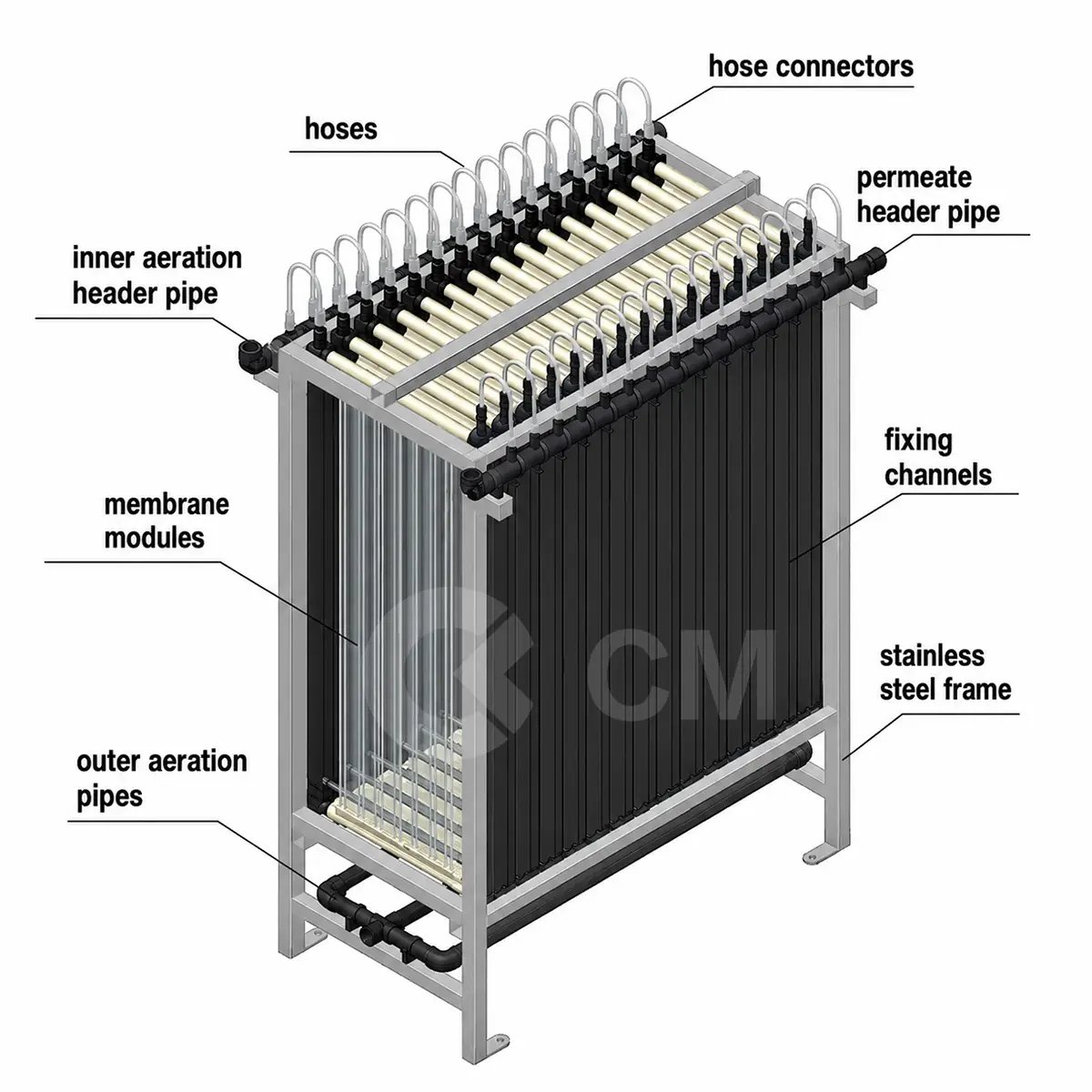
The structure shown in the diagram is a typical submerged hollow-fiber MBR membrane rack. Multiple membrane modules are installed inside a stainless-steel frame. Each module connects to a permeate header through an individual hose, while air is introduced beneath the modules to scour the membrane surface and control fouling.
This article explains each part of the MBR membrane frame and provides preliminary design values that engineers can use when evaluating or configuring an MBR system.
Engineering note: The values in this article are typical preliminary-design ranges rather than universal limits. Final membrane flux, air demand, module spacing, pipe diameter, cleaning pressure, and structural dimensions must be verified against the selected membrane manufacturer’s design manual, wastewater characteristics, pilot-test results, and local engineering standards.
1. Main Components of an MBR Membrane Frame
A complete submerged MBR membrane rack normally includes:
- Membrane modules
- Stainless-steel supporting frame
- Permeate hoses
- Hose connectors
- Permeate header pipe
- Internal aeration header
- External aeration pipes
- Module fixing channels
- Bottom support structure
- Lifting and positioning points
- Isolation valves and instrument connections
These components form an integrated filtration unit that can be installed directly in an MBR membrane tank.
2. MBR Membrane Modules
The membrane modules are the main solid–liquid separation components of the system.
Under suction from the permeate pump, treated water passes through the membrane surface and enters the internal permeate channels. Activated sludge, suspended solids, colloidal particles, and most microorganisms remain in the membrane tank.
Unlike a conventional activated-sludge process, an MBR system does not depend on secondary clarification for final solids separation. The membrane acts as a physical barrier, allowing the biological reactor to operate at a relatively high mixed liquor suspended solids concentration. DuPont notes that MBR systems may operate at approximately 8,000–15,000 mg/L MLSS, although many municipal projects use a more conservative range to improve oxygen transfer and reduce viscosity.
Common membrane configurations
The most common MBR membrane configurations are:
- Hollow-fiber MBR membranes
- Flat-sheet MBR membranes
- Tubular membranes
- Ceramic membranes for special industrial applications
The illustrated rack is most similar to a submerged hollow-fiber configuration because it uses multiple narrow membrane modules connected individually to a permeate manifold.
Typical preliminary membrane design values
| Parameter | Typical municipal wastewater range | Industrial wastewater consideration |
|---|---|---|
| Nominal membrane pore size | 0.03–0.4 μm | Confirm based on membrane material and treatment objective |
| Average net operating flux | 10–25 LMH | Often 6–18 LMH for difficult wastewater |
| Peak net flux | 20–35 LMH | Peak operation should be limited and verified by testing |
| MLSS in membrane tank | 6,000–12,000 mg/L | Commonly 8,000–15,000 mg/L where higher solids are required |
| Typical operating TMP | 5–30 kPa | May increase faster with oily, saline, viscous, or high-fouling wastewater |
| Temperature correction basis | Usually 20°C or 25°C | Low temperature reduces permeability |
| Membrane recovery | Commonly above 90% | Depends on backwash, relaxation, maintenance cleaning, and sludge wasting |
LMH means litres per square metre of membrane area per hour.
These ranges should not be used to select membrane area without considering temperature, peak flow, fouling potential, cleaning downtime, train redundancy, and membrane ageing.
3. Stainless-Steel Membrane Frame
The stainless-steel frame supports the membrane modules, permeate pipework, aeration headers, and lifting loads.
Because the rack remains submerged in activated sludge for long periods, it must resist:
- Corrosion
- Aeration-induced vibration
- Hydrostatic loading
- Lifting and transportation forces
- Module weight
- Pipe reaction forces
- Repeated maintenance operations
Common frame materials
| Wastewater condition | Common material selection |
|---|---|
| Normal municipal wastewater | 304 or 304L stainless steel |
| Higher chloride concentration | 316 or 316L stainless steel |
| Coastal, saline, or corrosive industrial wastewater | 316L, duplex stainless steel, or specially protected material |
| Strongly acidic or alkaline wastewater | Material selection based on corrosion analysis |
| High chemical-cleaning exposure | Confirm compatibility with cleaning chemicals and concentration |
Material selection should be based on chloride concentration, pH, temperature, cleaning chemicals, dissolved sulphides, and industrial contaminants. Using 304 stainless steel without checking chloride exposure can lead to pitting or crevice corrosion.
Structural design considerations
The frame should be checked for:
-
Dry lifting load
Weight of the frame, membrane modules, pipework, and fittings. -
Wet lifting load
Residual liquid and sludge may remain inside the rack during removal. -
Dynamic lifting factor
A design allowance is required for crane movement, impact, and uneven lifting. -
Operational vibration
Coarse-bubble aeration produces repeated movement and cyclic loading. -
Module restraint
Modules must not collide with one another during operation. -
Base support
The rack must remain level and stable in the membrane tank.
Typical preliminary structural allowances
| Item | Preliminary recommendation |
|---|---|
| Design lifting factor | 1.25–1.50 times the calculated lifted load |
| Recommended access around removable rack | 500–800 mm where tank layout permits |
| Clearance above rack for lifting | Rack height plus lifting beam, hook, and safe rigging allowance |
| Frame deflection | Keep sufficiently low to prevent module, hose, or header misalignment |
| Anchor or guide tolerance | Confirm against rack installation drawings |
| Lifting points | Normally at least four balanced lifting points for large racks |
The exact safety factor and structural design method must comply with the applicable local structural and lifting standards.
4. Membrane Module Fixing Channels
The fixing channels hold each membrane module in its correct position.
They prevent excessive movement caused by:
- Air scouring
- Mixed-liquor circulation
- Pump start and stop
- Rack lifting
- Tank turbulence
Correct module spacing is important because the rising air and mixed liquor need a clear path between adjacent modules.
Why spacing matters
If the modules are too close:
- Air may not distribute evenly.
- Sludge can accumulate between modules.
- Dead zones may develop.
- Local TMP may increase.
- Chemical cleaning may become less effective.
- Individual modules may be difficult to remove.
If the spacing is excessive:
- Membrane packing density decreases.
- The membrane tank becomes larger.
- Civil construction cost increases.
- Air may bypass the membrane surfaces.
Typical module-spacing guidance
There is no single universal spacing because module geometry varies substantially. For preliminary mechanical layouts:
| Design item | Typical preliminary allowance |
|---|---|
| Clear space between narrow module bodies | Approximately 20–80 mm |
| Clearance between outer module and rack frame | Approximately 30–100 mm |
| Bottom clearance above air diffuser | Commonly 150–500 mm |
| Maintenance clearance for module removal | Based on connector, hose, and lifting arrangement |
The final dimensions must be taken from the membrane supplier’s installation drawing. Kubota, for example, emphasises that the geometry of the membrane cartridge and the available scouring-flow path strongly affect air-cleaning performance.
5. Permeate Hoses
Each membrane module is connected to the permeate collection system through a flexible hose.
The hose transports filtered water from the module outlet to the permeate header. Using an individual hose for each module also makes it easier to isolate, inspect, test, or replace a single membrane module.
Permeate hose requirements
A suitable hose should have:
- Adequate vacuum resistance
- Low permeability to air
- Chemical resistance
- Resistance to repeated bending
- A smooth internal surface
- Reliable connection under vibration
- Compatibility with sodium hypochlorite, citric acid, or other approved cleaning chemicals
Typical design checks
| Parameter | Preliminary recommendation |
|---|---|
| Hose velocity | Normally below approximately 1.0–1.5 m/s |
| Hose bend radius | At least the manufacturer’s minimum bend radius |
| Hose length | Keep similar among parallel modules where practical |
| Hose routing | Avoid kinks, trapped air, sharp edges, and contact with moving parts |
| Vacuum rating | Greater than the maximum expected suction pressure |
| Connection arrangement | Tool-free or easily serviceable where possible |
A collapsed, kinked, blocked, or leaking hose may cause uneven filtration across the rack.
| Symptom | Possible cause |
|---|---|
| One module has low permeate flow | Kinked hose, blocked connector, fouled module |
| Air enters the permeate line | Loose connector or cracked hose |
| Unstable suction pressure | Air leakage, pump cavitation, or header venting problem |
| Uneven rack loading | Different hose resistance or partial blockage |
| Repeated hose failure | Incorrect material, excessive bending, vibration, or chemical attack |
6. Hose Connectors
Hose connectors join the membrane outlet to the flexible permeate hose.
Although small, they are critical to the airtightness of the permeate system. A minor air leak can reduce suction stability and make membrane-performance data difficult to interpret.
Connector design requirements
- Secure mechanical engagement
- Good vacuum sealing
- Chemical resistance
- Easy disassembly
- Resistance to vibration
- Low internal pressure loss
- Replaceable seals or O-rings
Recommended engineering checks
- Confirm the connector material is compatible with the cleaning chemicals.
- Avoid unsupported hose weight acting directly on the membrane outlet.
- Provide strain relief where necessary.
- Check O-rings during each major maintenance inspection.
- Perform a low-pressure or vacuum leak test after reassembly.
- Do not overtighten plastic membrane ports.
7. Permeate Header Pipe
The permeate header collects filtered water from all membrane modules in the rack.
Water flows from the individual modules through the hoses and then into the common header. From there, it is transferred to the permeate pump, clean-water tank, disinfection system, or downstream reuse process.
Main functions of the permeate header
- Collect permeate from parallel modules
- Minimise hydraulic imbalance
- Connect the rack to the suction pump
- Provide a flow path for backwashing
- Distribute maintenance-cleaning solution
- Allow pressure measurement and integrity testing
Preliminary header-sizing criteria
| Parameter | Typical preliminary range |
|---|---|
| Normal permeate velocity | 0.6–1.5 m/s |
| Maximum short-duration backwash velocity | Commonly up to 1.5–2.0 m/s |
| Allowable rack-header pressure loss | Preferably less than 5–10% of normal operating TMP |
| Minimum high-point venting | Required where air can accumulate |
| Drain connection | Recommended at low points |
| Pressure or vacuum gauge | Recommended for each filtration train |
| Isolation valve | Recommended for each rack or rack group |
A header that is too small produces excessive pressure loss. Modules near the pump connection may then operate at a different effective TMP from modules at the far end of the rack.
Example permeate-header calculation
Assume:
- Membrane area per rack: 1,000 m²
- Net design flux: 18 LMH
- Rack permeate flow:
$$ Q = A \times J $$
$$
Q = 1{,}000 \times 18 = 18{,}000 \text{ L/h}
$$
$$
Q = 18 \text{ m}^3/\text{h}
$$
For a target header velocity of 1.0 m/s:
$$
D = \sqrt{\frac{4Q}{\pi v}}
$$
Convert flow to m³/s:
$$
Q = \frac{18}{3600}=0.005 \text{ m}^3/\text{s}
$$
$$
D = \sqrt{\frac{4 \times 0.005}{3.1416 \times 1.0}}
$$
$$
D \approx 0.080 \text{ m}
$$
The calculated internal diameter is approximately 80 mm. After checking backwash flow, fittings, pipe roughness, available standard sizes, and allowable pressure loss, an engineer might preliminarily select a nominal pipe around DN80 or DN100.
This is only a hydraulic example. The final pipe size must be checked using the actual internal pipe diameter and full pressure-loss calculation.
8. Internal Aeration Header
The internal aeration header distributes air to the diffuser or aeration pipes below the membrane modules.
The rising air bubbles create a mixed-liquor circulation pattern and provide membrane-surface scouring. This helps reduce solids deposition and slows the increase in transmembrane pressure.
DuPont describes continuous airflow distributed directly to aeration devices at the bottom of its MBR modules. Kubota similarly identifies membrane-scouring airflow, flux, MLSS, filtration pressure, and water temperature as key operating variables affecting fouling and TMP behaviour.
Main functions of membrane aeration
- Scour solids from the membrane surface
- Reduce cake-layer formation
- Promote crossflow around the membrane
- Limit sludge accumulation inside the rack
- Maintain mixing in the membrane zone
- Contribute some oxygen to the biological process
The air used for membrane scouring should not automatically be assumed to meet the entire biological oxygen demand. Large MBR facilities may use separate membrane-scouring and biological aeration systems so that each airflow can be controlled independently.
Typical preliminary air-scouring values
Aeration requirements differ significantly among membrane technologies. Preliminary ranges for conventional submerged MBR modules are:
| Parameter | Typical preliminary range |
|---|---|
| Specific aeration demand per membrane area, SADm | 0.20–0.60 Nm³/m²·h |
| Specific aeration demand per permeate volume, SADp | 5–20 Nm³ air/m³ permeate |
| Air-header velocity | Approximately 8–15 m/s |
| Branch-pipe velocity | Approximately 5–10 m/s |
| Air pressure at blower discharge | Static water depth + diffuser loss + pipe loss + control margin |
| Typical membrane-tank water depth | Approximately 3–5.5 m, depending on module |
| Airflow turndown | Preferably available for low-flow operation |
Newer proprietary low-energy systems may use substantially less air than older continuous-aeration designs. For example, DuPont reports major aeration-energy reductions for its pulsed-air MemPulse configuration, which means a generic aeration value should never be substituted for the supplier’s certified requirement.
Air-pressure calculation
A preliminary blower discharge pressure can be estimated as:
$$
P{blower}=P{static}+P{diffuser}+P{pipe}+P{valve}+P{margin}
$$
For example:
- Submergence depth: 4.5 m
- Static pressure: approximately 44 kPa
- Diffuser loss: 8 kPa
- Pipe and valve loss: 5 kPa
- Control margin: 8 kPa
$$
P_{blower}=44+8+5+8=65\text{ kPa}
$$
The blower would therefore need to deliver the required airflow at approximately 65 kPa gauge pressure, subject to actual site altitude, temperature, air density, fouling allowance, and manufacturer curves.
9. External Aeration Pipes
The external aeration pipes connect the membrane rack to the main air supply.
A typical air system may include:
- Duty and standby blowers
- Main air header
- Rack branch pipes
- Isolation valves
- Flow-control valves
- Check valves
- Flexible connectors
- Pressure transmitters
- Airflow meters
- Drain connections
Important design points
Balance the airflow
Each rack or membrane train should receive the required air quantity. Without balancing valves or flow measurement, racks close to the blower may receive excessive air while remote racks receive insufficient air.
Prevent water entry
Air pipes may fill with mixed liquor when the blower stops. The design should therefore consider:
- Check valves
- High-point routing
- Drain points
- Purge cycles
- Restart pressure
- Anti-siphon arrangements
Limit pressure loss
Avoid unnecessary bends, undersized branch lines, and abrupt reductions. High pressure loss increases blower energy consumption and reduces airflow stability.
Provide isolation
Each rack should preferably be isolatable for inspection, cleaning, or removal without shutting down the entire membrane train.
10. How the MBR Membrane Frame Operates
The rack operates through four coordinated processes.
10.1 Biological treatment
Screened and pretreated wastewater enters the biological reactor. Microorganisms convert organic contaminants and, where required, remove nitrogen and phosphorus.
10.2 Membrane filtration
The permeate pump creates a low vacuum on the clean side of the membrane. Water passes through the membrane while biomass and suspended solids remain in the reactor.
10.3 Permeate collection
Filtered water moves through the module outlets, flexible hoses, and common permeate header.
10.4 Air scouring
Air introduced beneath the modules rises through the membrane bundle. The bubbles and liquid circulation reduce solids accumulation on the membrane surface.
Filtration may be operated continuously or intermittently with programmed relaxation and backwash periods.
11. Typical MBR Filtration Cycle
The exact cycle depends on the selected membrane system. A preliminary cycle may look like the following:
| Operating stage | Typical duration |
|---|---|
| Filtration | 8–12 minutes |
| Relaxation | 0.5–2 minutes |
| Backwash, where applicable | 20–60 seconds |
| Maintenance clean | Daily to weekly, depending on membrane and wastewater |
| Recovery clean | Every few months or when performance reaches the supplier’s trigger |
Some flat-sheet membranes operate mainly by filtration and relaxation without routine hydraulic backwashing. Many hollow-fiber systems use a combination of filtration, relaxation, backpulse, maintenance cleaning, and periodic recovery cleaning.
The operating sequence must therefore be based on the specific membrane design.
12. Key MBR Design Parameters
12.1 Design flow
Membrane sizing should consider:
- Average daily flow
- Maximum daily flow
- Peak hourly flow
- Minimum operating flow
- Equalisation capacity
- Number of operating trains
- Standby membrane capacity
- Cleaning and maintenance downtime
12.2 Membrane area calculation
The preliminary net membrane area can be estimated using:
$$
A=\frac{Q}{J}
$$
Where:
- (A) = required membrane area, m²
- (Q) = net permeate flow, L/h
- (J) = selected net design flux, L/m²·h
Example
Required net production:
$$
Q=1{,}000\text{ m}^3/\text{day}
$$
Convert to hourly flow:
$$
Q=\frac{1{,}000}{24}=41.67\text{ m}^3/\text{h}
$$
At a net design flux of 18 LMH:
$$
A=\frac{41{,}670}{18}=2{,}315\text{ m}^2
$$
Apply a preliminary 15% allowance for ageing, maintenance, and operating uncertainty:
$$
A_{design}=2{,}315\times1.15=2{,}662\text{ m}^2
$$
The preliminary installed membrane area would therefore be approximately 2,700 m².
A more rigorous design must separately account for peak flow, offline cleaning, temperature correction, backwash water, relaxation time, and the number of trains.
13. Net Flux Versus Gross Flux
Engineers should distinguish between gross filtration flux and net production flux.
Gross flux
$$
J_g=\frac{\text{Instantaneous filtration flow}}{\text{Membrane area}}
$$
Net flux
$$
J_n=\frac{\text{Net daily permeate production}}{\text{Membrane area}\times24}
$$
Net production excludes:
- Backwash water
- Relaxation time
- Maintenance-cleaning downtime
- Recovery-cleaning downtime
- Off-specification permeate
- Integrity-test water
For this reason, sizing a system only with instantaneous gross flux may underestimate the required membrane area.
14. Transmembrane Pressure
TMP represents the pressure difference driving water through the membrane.
For a suction-operated submerged membrane:
$$
TMP=P{mixed\ liquor}-P{permeate}
$$
Because the mixed-liquor side is close to atmospheric pressure, TMP is often approximated from the permeate-side vacuum after correcting for elevation and pipe losses.
Typical interpretation
| TMP condition | General interpretation |
|---|---|
| 5–15 kPa | Clean or normally operating membrane |
| 15–30 kPa | Increasing resistance; review fouling trend |
| 30–50 kPa | Cleaning or detailed investigation may be required |
| Above supplier limit | Risk of compaction, damage, poor operation, or loss of production |
These values are broad operating indicators only. The membrane manufacturer’s maximum TMP and cleaning trigger always take priority.
TMP should be temperature-corrected when comparing performance over time, because colder water has higher viscosity and produces lower permeability.
15. Membrane Permeability
Permeability provides a more useful performance indicator than TMP alone:
$$
Permeability=\frac{Flux}{TMP}
$$
The units are commonly:
$$
LMH/bar
$$
or
$$
LMH/kPa
$$
Example
- Flux: 18 LMH
- TMP: 15 kPa
$$
Permeability=\frac{18}{15}=1.2\text{ LMH/kPa}
$$
A sustained decline in temperature-corrected permeability may indicate:
- Membrane fouling
- Scaling
- Organic deposition
- Insufficient aeration
- Sludge accumulation
- Fibre blockage
- Inadequate cleaning
- Increased mixed-liquor viscosity
16. Recommended MBR Tank and Rack Layout Checks
The membrane-tank layout should be reviewed for the following points.
| Layout item | Engineering objective |
|---|---|
| Rack spacing | Allow even circulation and maintenance access |
| Tank floor level | Prevent rack tilting |
| Air diffuser position | Distribute bubbles through the active membrane zone |
| Freeboard | Prevent overflow and excessive foam carryover |
| Minimum operating level | Keep modules fully submerged |
| High-water level | Avoid flooding non-submersible connectors or instruments |
| Drainage | Allow tank cleaning and sludge removal |
| Lifting access | Permit vertical rack removal |
| Crane capacity | Include wet weight and dynamic allowance |
| Pipe flexibility | Avoid loading the rack during installation or lifting |
| Isolation | Allow one train or rack to be serviced |
| Bypass and redundancy | Maintain treatment during cleaning or maintenance |
Typical preliminary clearances
| Item | Preliminary range |
|---|---|
| Rack-to-rack side clearance | 100–500 mm, subject to supplier layout |
| Rack-to-tank-wall clearance | 200–600 mm |
| Clearance below rack | 150–500 mm |
| Liquid level above upper membrane surface | 200–500 mm minimum |
| Tank freeboard | Commonly 500–1,000 mm |
| Main operator walkway | Commonly at least 800–1,000 mm |
Manufacturer drawings take priority because some cassette systems are intentionally installed with smaller spacing to create a controlled circulation pattern.
17. Preliminary MBR Process Design Ranges
The following table provides a practical starting point for municipal wastewater design.
| Design parameter | Typical preliminary range |
|---|---|
| Fine-screen opening before hollow-fiber MBR | 1–3 mm |
| Fine-screen opening before flat-sheet MBR | 2–3 mm, sometimes larger if approved |
| MLSS | 6,000–12,000 mg/L |
| MLVSS/MLSS ratio | 0.65–0.85 |
| Sludge retention time | 15–40 days |
| Hydraulic retention time | 4–12 hours |
| Dissolved oxygen in aerobic membrane zone | 1.5–3.0 mg/L |
| Average net membrane flux | 10–25 LMH |
| Peak net membrane flux | 20–35 LMH |
| Normal TMP | 5–30 kPa |
| Membrane-tank pH | Commonly 6.5–8.5 |
| Normal operating temperature | Approximately 10–35°C |
| Membrane-zone MLSS upper limit | Confirm supplier; often 12,000–15,000 mg/L |
| SADm | Approximately 0.20–0.60 Nm³/m²·h |
| Membrane-train redundancy | At least one train or sufficient reserve capacity for maintenance |
Industrial wastewater may require lower flux, more equalisation, oil and grease removal, chemical pretreatment, temperature control, and pilot testing.
18. Pretreatment Requirements
Membrane-frame performance depends heavily on the upstream pretreatment system.
Typical pretreatment may include:
- Coarse screening
- Grit removal
- Oil separation
- Equalisation
- Fine screening
- pH adjustment
- Temperature control
- Primary solids removal where required
Fine-screen design
For hollow-fiber MBR systems, a fine screen of approximately 1–3 mm is commonly used as a preliminary design range. Fibres, hair, plastic strips, and other stringy materials can wrap around membrane bundles or block the lower aeration zone.
The screen type should also be evaluated. A two-dimensional perforated-plate or drum screen can provide more reliable protection against fibres than a one-dimensional bar screen with the same nominal opening.
Screen bypasses must be avoided because even a short bypass event can introduce debris that remains inside the membrane rack for a long time.
19. Operational Monitoring
Each membrane train should monitor at least the following parameters:
| Parameter | Recommended monitoring frequency |
|---|---|
| Permeate flow | Continuous |
| TMP or suction pressure | Continuous |
| Membrane-tank level | Continuous |
| Airflow to each train | Continuous or regular verification |
| Permeate turbidity | Continuous where integrity is critical |
| MLSS | Daily to several times per week |
| Dissolved oxygen | Continuous |
| Temperature | Continuous |
| pH | Continuous or daily |
| Permeability | Automatically calculated or reviewed daily |
| Ammonia and COD | According to treatment objectives |
| Sludge viscosity or filterability | Periodic troubleshooting test |
| Hose and connector condition | Visual inspection during maintenance |
Kubota’s recent MBR operating work identifies filtration pressure, filtration flow, scouring airflow, water temperature, and optionally MLSS as important variables for predicting TMP development.
20. Common Problems Related to the Membrane Frame
Uneven air distribution
Possible causes:
- Blocked aeration holes
- Incorrect valve settings
- Water trapped in an air pipe
- Damaged diffuser
- Insufficient blower pressure
- Poor air-header balancing
Possible consequences:
- Local sludge accumulation
- Rapid TMP increase
- Uneven membrane ageing
- Higher chemical-cleaning frequency
Uneven permeate withdrawal
Possible causes:
- Undersized permeate header
- Different hose lengths
- Blocked hose or connector
- Air leakage
- Incorrect valve position
Possible consequences:
- Overloading of selected modules
- Localised fouling
- Reduced rack capacity
- Misleading average TMP data
Rack vibration or movement
Possible causes:
- Loose fixing channels
- Excessive aeration
- Insufficient frame stiffness
- Incorrect base alignment
- Damaged support points
Possible consequences:
- Hose fatigue
- Connector leakage
- Membrane damage
- Weld cracking
Sludge accumulation below the rack
Possible causes:
- Insufficient bottom velocity
- Poor diffuser positioning
- Inadequate tank mixing
- Low-air operation for extended periods
- Dead space below the frame
Possible consequences:
- Anaerobic sludge zones
- Odour
- Uneven aeration
- Solids carryover during maintenance
- Accelerated membrane fouling
21. Maintenance Inspection Checklist
Daily or routine checks
- Confirm stable permeate flow.
- Review TMP and permeability trends.
- Check membrane air-scouring flow.
- Observe whether aeration is visually uniform.
- Verify permeate turbidity.
- Check membrane-tank level.
- Confirm no unusual pump or blower vibration.
Weekly checks
- Inspect visible hoses and connectors.
- Compare airflow between racks.
- Check valve positions.
- Review chemical-cleaning frequency.
- Inspect for foam or sludge accumulation.
- Verify instrument readings against local gauges.
During planned shutdown
- Inspect hose flexibility and cracking.
- Replace damaged O-rings.
- Check fixing channels and module restraints.
- Inspect stainless-steel welds.
- Check rack alignment.
- Clean aeration openings.
- Inspect lifting points.
- Confirm the permeate header is not blocked.
- Perform an integrity test where required.
22. How Good Frame Design Improves MBR Performance
A well-designed MBR membrane frame provides several practical benefits:
- More uniform membrane flux
- Better airflow distribution
- Lower local fouling rates
- More stable TMP
- Reduced unnecessary aeration
- Easier module replacement
- Faster chemical cleaning
- Lower maintenance labour
- Improved structural reliability
- Better system availability
The membrane material controls separation, but the rack, headers, hoses, aeration layout, and module spacing determine how consistently the membrane performs in real operating conditions.
23. Engineering Design Summary
When selecting or designing an MBR membrane rack, engineers should confirm the following information with the membrane supplier:
| Required information | Why it matters |
|---|---|
| Membrane area per module | Determines rack capacity |
| Recommended average and peak flux | Determines installed membrane area |
| Maximum operating TMP | Protects membrane integrity |
| Design MLSS range | Affects viscosity and fouling |
| Required air-scouring flow | Determines blower and air-pipe size |
| Module dimensions and spacing | Determines frame and tank size |
| Maximum number of modules per rack | Determines hydraulic and structural configuration |
| Required filtration cycle | Affects net production |
| Backwash flow and pressure | Determines pump and header size |
| Chemical-cleaning concentration | Determines material compatibility |
| Wet and dry rack weight | Determines lifting equipment |
| Minimum submergence | Determines tank operating level |
| Recommended pretreatment screen | Protects membrane modules |
| Integrity-test method | Supports effluent-quality assurance |
| Expected design life | Supports lifecycle-cost evaluation |
DuPont, for example, offers rack configurations containing multiple modules and describes modular rack arrangements intended to simplify installation, maintenance, and replacement.
Conclusion
An MBR membrane frame is an integrated filtration assembly consisting of membrane modules, permeate hoses, connectors, collection headers, aeration pipes, fixing channels, and a supporting frame.
Each part affects the long-term performance of the MBR system:
- The membrane modules provide solids separation.
- The permeate hoses and header collect treated water.
- The aeration system controls surface deposition and sludge accumulation.
- The fixing channels maintain module spacing.
- The stainless-steel frame provides structural stability and allows the rack to be lifted and maintained.
For reliable engineering design, membrane area should be calculated using net flux rather than only instantaneous filtration flux. The aeration system should be based on the selected membrane supplier’s certified airflow requirement. Permeate and air headers should be sized through hydraulic calculations, while the frame should be checked for corrosion, vibration, wet lifting load, and maintenance access.
A membrane product should therefore not be evaluated only by membrane area or unit price. Engineers should also compare flux limitations, aeration demand, header design, rack material, module replacement method, cleaning requirements, structural reliability, and lifecycle operating cost.