
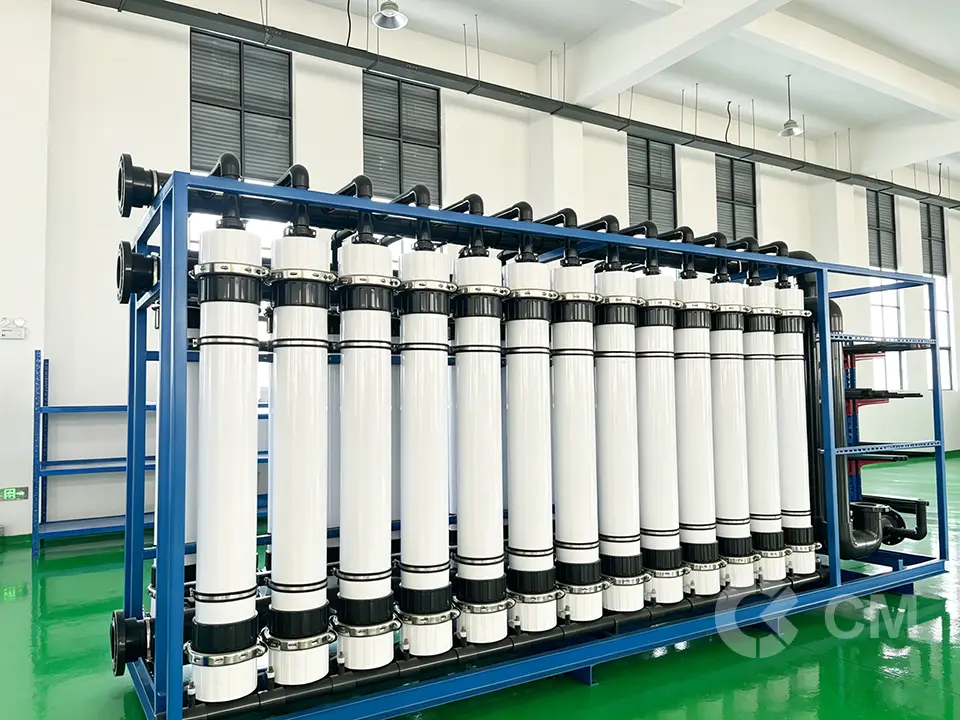
Ultrafiltration membrane systems are widely used in industrial water treatment, RO pretreatment, wastewater reuse, seawater desalination pretreatment and process water filtration. A well-designed UF system can provide stable turbidity removal, suspended solids separation and reliable protection for downstream RO or NF membranes.
However, during long-term operation, UF membranes may face different problems such as increasing transmembrane pressure, reduced permeate flow, poor backwash recovery, unstable filtrate turbidity, fiber breakage or frequent chemical cleaning. If these problems are not diagnosed correctly, operators may increase cleaning frequency, replace chemicals, adjust pressure or even replace modules without solving the real cause.
UF membrane troubleshooting should not be based on one single symptom. A correct diagnosis requires checking feed water quality, operating data, pressure trends, cleaning performance, system design and membrane condition.
This guide explains the most common UF membrane problems, their possible causes and practical troubleshooting methods for industrial water treatment projects.
Why UF Membrane Troubleshooting Matters
UF membranes are often used as a critical pretreatment step before reverse osmosis systems. If the UF system becomes unstable, downstream RO membranes may quickly suffer from fouling, high differential pressure, frequent cleaning and reduced membrane life.
For industrial users and engineering companies, UF membrane problems may cause:
- Lower water production
- Higher operating pressure
- Increased chemical consumption
- More frequent cleaning
- Shorter membrane lifespan
- Poor RO pretreatment performance
- Higher turbidity or SDI in UF filtrate
- Unplanned shutdowns
- Increased operating cost
- Failure to meet project water quality requirements
In many cases, the membrane module is not the only cause. Problems may come from poor pretreatment, incorrect design flux, unsuitable chemical dosing, insufficient backwash, poor air scouring, pressure shock, bad operation or changing feed water quality.
A systematic troubleshooting process can help determine whether the problem can be solved by operation adjustment, chemical cleaning, pretreatment improvement or membrane replacement.
Quick UF Membrane Troubleshooting Table
| Problem | Common Symptoms | Possible Causes | Recommended Action |
|---|---|---|---|
| High TMP | Pressure keeps increasing under same flow | Fouling, scaling, blocked fibers, insufficient backwash | Check normalized permeability, improve cleaning, review feed water |
| Low permeate flow | Water production decreases | Fouling, pump issue, valve issue, blocked strainer, high TMP | Check pressure, flow meter, valves, cleaning recovery |
| High filtrate turbidity | UF outlet water becomes unclear | Fiber breakage, sealing leakage, module damage | Perform integrity test and check module condition |
| Frequent backwash | Filtration cycle becomes shorter | High solids load, poor pretreatment, excessive flux | Improve pretreatment or reduce design flux |
| CEB not effective | TMP rises quickly after cleaning | Wrong chemical, low dosage, short contact time, severe fouling | Identify fouling type and optimize cleaning |
| CIP cannot recover performance | Flow and TMP do not improve after CIP | Irreversible fouling, chemical damage, aging, fiber blockage | Evaluate replacement |
| Fiber breakage | Turbidity leakage or integrity failure | Pressure shock, air scouring damage, chemical attack, aging | Isolate damaged module and replace if needed |
| Air scouring problem | Cleaning effect poor or fibers damaged | Uneven air distribution, excessive air flow, blocked air pipe | Check air system and operating settings |
| Biofouling | Slimy deposits, odor, rapid TMP increase | Biological growth, insufficient disinfection | Adjust biocide/CEB and improve pretreatment |
| Chemical damage | Sudden performance change, weak fibers | Wrong chemicals, excessive oxidant, pH beyond limit | Stop chemical exposure and check membrane compatibility |
Key Operating Data to Check Before Troubleshooting
Before making any conclusion, operators should collect basic operating data. Without data, UF troubleshooting becomes guesswork.
Important data includes:
- Feed water source
- Feed turbidity
- Feed suspended solids
- Feed COD or TOC
- Oil and grease content
- Iron and manganese concentration
- Feed pressure
- Permeate pressure
- TMP trend
- Permeate flow trend
- Recovery rate
- Backwash frequency
- Backwash pressure
- Air scouring condition
- CEB chemical type and concentration
- CIP chemical type and concentration
- Filtrate turbidity
- SDI before RO
- Temperature
- pH
- Operating hours
- Membrane module model and service time
For engineering troubleshooting, trends are more important than single readings. A gradual TMP increase over several weeks usually indicates fouling accumulation. A sudden pressure change may indicate valve problems, pump problems, blockage, pressure shock or module damage.
Problem 1: UF Membrane TMP Keeps Increasing
High TMP is one of the most common UF membrane problems. TMP, or transmembrane pressure, represents the pressure difference across the membrane. When TMP increases under the same flow rate, it usually means membrane resistance is increasing.
Common symptoms:
- Feed pressure becomes higher
- Permeate flow decreases under the same pump condition
- Filtration cycle becomes shorter
- Backwash cannot fully recover pressure
- CEB frequency increases
- CIP is needed more often
- Downstream RO SDI may become unstable
Possible causes:
- Suspended solids overload
- Organic fouling
- Biofouling
- Inorganic scaling
- Iron or manganese fouling
- Oil or grease contamination
- Insufficient backwash
- Poor air scouring
- Excessive design flux
- Incorrect chemical cleaning
- Feed water quality change
- Blocked prefilter or strainer
- Valve operation error
Troubleshooting steps:
First, confirm whether the TMP increase is gradual or sudden. A gradual increase usually indicates fouling. A sudden increase may indicate a mechanical or hydraulic problem.
Second, check whether the permeate flow is stable. If the system is running at constant flow, TMP will rise when fouling increases. If the system is running at constant pressure, permeate flow will drop when fouling increases.
Third, check whether backwash and CEB can recover permeability. If TMP returns close to normal after cleaning but rises again quickly, the feed water load may be too high or the cleaning strategy may not be sufficient. If cleaning cannot recover TMP, severe or irreversible fouling may already exist.
Fourth, check feed water turbidity, COD, iron, manganese, hardness and oil content. These indicators can help identify the fouling type.
Engineering suggestions:
- Reduce operating flux if the system is overloaded
- Increase backwash frequency for high turbidity water
- Check backwash pump flow and pressure
- Verify air scouring distribution
- Optimize CEB chemical type and contact time
- Use acid cleaning for inorganic scaling if compatible
- Use alkaline or oxidant cleaning for organic and biological fouling if compatible
- Improve pretreatment before UF
- Check whether the membrane has reached replacement condition
If TMP remains high after correct CIP, membrane replacement may be required.
Problem 2: UF Permeate Flow Becomes Low
Low permeate flow is another common UF system problem. It may be caused by membrane fouling, but it can also be caused by pumps, valves, flow meters, air accumulation or system control issues.
Common symptoms:
- UF system output decreases
- Permeate flow cannot reach design capacity
- Feed pressure increases
- Production time becomes longer
- Downstream RO system lacks feed water
- System frequently alarms for low flow
Possible causes:
- Membrane fouling
- High TMP
- Feed pump performance decline
- Blocked feed strainer
- Incorrect valve position
- Air trapped in the module or pipeline
- Flow meter error
- Low feed tank level
- Insufficient feed pressure
- Excessive recovery rate
- Low water temperature
- Severe fiber blockage
- Module aging
Troubleshooting steps:
Start by checking whether the low flow is accompanied by high TMP. If TMP is high, the main problem is usually membrane fouling or blockage. If TMP is not high, the problem may be related to pump performance, valves, instrumentation or feed water supply.
Check the feed pump curve and actual operating pressure. A pump may still run but fail to provide enough flow due to wear, cavitation, impeller damage or low suction pressure.
Check all automatic valves and manual valves. In many UF systems, one partially closed valve can cause major flow reduction.
Check whether backwash, forward flush and filtration valves switch correctly. A control error may cause internal bypass or flow restriction.
Check water temperature. Low temperature increases water viscosity and reduces membrane permeability. If the system was designed based on warm water but operates in cold seasons, flow reduction may be normal unless corrected by design margin.
Engineering suggestions:
- Compare current normalized permeability with historical data
- Inspect feed pump and suction condition
- Clean strainers and prefilters
- Check valve sequence and PLC logic
- Perform backwash and CEB
- Conduct CIP if fouling is confirmed
- Reduce flux temporarily
- Check for air blockage
- Evaluate membrane aging if recovery is poor
Low flow should not be solved simply by increasing pressure. Increasing pressure without solving fouling can accelerate membrane damage.
Problem 3: UF Filtrate Turbidity Is High
UF membranes are expected to provide stable low-turbidity filtrate. If UF filtrate turbidity increases, the issue should be taken seriously, especially when UF is used before RO systems.
Common symptoms:
- UF permeate becomes cloudy
- Turbidity readings increase
- Downstream RO SDI increases
- RO cartridge filters block quickly
- Filtrate quality fluctuates
- Integrity test fails
- Turbidity increases after backwash or air scouring
Possible causes:
- Fiber breakage
- Membrane module damage
- Potting leakage
- O-ring or sealing failure
- Incorrect valve position
- Cross-contamination during backwash
- Air scouring damage
- Pressure shock
- Chemical damage
- Poor installation or module handling
Troubleshooting steps:
First, confirm whether the turbidity increase is continuous or intermittent. Continuous turbidity leakage may indicate fiber breakage or sealing failure. Intermittent turbidity spikes may occur after backwash, air scouring or valve switching.
Second, perform an integrity test if the system is equipped for it. Integrity testing can help identify whether membrane fibers or seals are compromised.
Third, isolate individual modules or racks to locate the problem source. If one module causes turbidity leakage, it should be removed, repaired if possible or replaced.
Fourth, check whether turbidity is caused by air bubbles rather than particles. Some turbidity meters may show unstable values when air bubbles enter the sample line.
Engineering suggestions:
- Check filtrate turbidity after each rack
- Perform pressure decay or integrity test
- Inspect O-rings and sealing parts
- Check module installation
- Isolate suspicious modules
- Replace damaged modules
- Review pressure shock and air scouring settings
- Avoid excessive pressure during backwash
High filtrate turbidity is a high-risk problem because it may allow particles to enter downstream RO membranes. If UF is used as RO pretreatment, the system should not continue operating normally until the leakage source is identified.
Problem 4: UF Membrane Fiber Breakage
Fiber breakage can cause filtrate turbidity leakage and reduce membrane separation reliability. In many cases, fiber breakage is related to mechanical stress, pressure shock, aging, chemical damage or improper operation.
Common causes of fiber breakage:
- Excessive pressure during filtration
- Sudden pressure shock
- Excessive backwash pressure
- Strong air scouring impact
- Poor module handling during installation
- Chemical corrosion
- Long-term aging
- Freezing damage
- Abrasive particles in feed water
- Repeated hydraulic stress
Common signs:
- Filtrate turbidity increases
- Integrity test fails
- Individual module leaks
- Permeate contains fine particles
- RO SDI increases after UF
- Turbidity spikes after backwash
Troubleshooting steps:
Identify whether fiber breakage is isolated or widespread. If only one module is damaged, it may be caused by installation, handling or local stress. If many modules show similar failure, the system may have design or operation problems.
Check pressure records. Sudden changes in feed pressure or backwash pressure may damage fibers. Pressure shock can occur when valves open or close too quickly.
Check air scouring settings. Uneven or excessive air scouring may cause membrane vibration and fiber fatigue.
Check chemical cleaning history. Exposure to incompatible chemicals or excessive oxidants may weaken membrane fibers.
Engineering suggestions:
- Control valve opening and closing speed
- Avoid sudden pressure shock
- Keep backwash pressure within recommended range
- Check air scouring distribution
- Use compatible cleaning chemicals
- Avoid dry storage or freezing
- Handle modules carefully during installation
- Replace damaged modules if integrity cannot be restored
Fiber breakage is not only a membrane quality issue. It is often related to system operation and hydraulic conditions.
Problem 5: Backwash Does Not Recover UF Performance
Backwash is designed to remove reversible fouling from the membrane surface or fiber channels. If backwash no longer restores performance, the fouling may have become more severe or the backwash system may not be working correctly.
Common symptoms:
- TMP continues to rise after backwash
- Permeate flow does not recover
- Filtration cycle becomes shorter
- Backwash water becomes very dirty
- Backwash pressure is unstable
- CEB is required more frequently
Possible causes:
- Backwash flow too low
- Backwash pressure too low
- Backwash time too short
- Backwash water quality poor
- Backwash valve malfunction
- Air scouring not working
- Fouling is no longer reversible
- Feed water solids load too high
- Design flux too high
- Membrane pores blocked by organic or inorganic matter
Troubleshooting steps:
Check whether the backwash pump is providing the required flow and pressure. A weak backwash pump will not remove accumulated solids effectively.
Check the backwash water source. If dirty water is used for backwash, contaminants may be pushed back into the membrane.
Check backwash valve operation. Incorrect valve sequence may reduce cleaning effect or cause cross-contamination.
Check whether air scouring is synchronized with backwash if the system uses air cleaning.
Compare TMP before and after backwash. If backwash recovery becomes worse over time, fouling is becoming less reversible.
Engineering suggestions:
- Restore correct backwash flow and pressure
- Increase backwash duration if suitable
- Check backwash water quality
- Clean or repair backwash valves
- Verify air scouring operation
- Add or optimize CEB
- Reduce filtration flux
- Improve feed pretreatment
- Perform CIP if backwash cannot restore performance
Backwash failure is often an early warning that the system needs process adjustment before severe fouling occurs.
Problem 6: CEB Is Not Effective
CEB, or chemically enhanced backwash, is used to improve fouling removal by adding chemicals during the backwash process. If CEB is not effective, the chemical type, dosage, contact time or fouling diagnosis may be incorrect.
Common symptoms:
- TMP rises quickly after CEB
- Permeability does not improve
- Chemical consumption increases
- CEB frequency becomes too high
- CIP is needed more often
- Fouling returns shortly after cleaning
Possible causes:
- Wrong chemical selected
- Chemical dosage too low
- Contact time too short
- pH not suitable
- Chemical pump failure
- Chemical tank concentration wrong
- Severe fouling beyond CEB recovery
- Biofouling not controlled
- Inorganic scaling treated with wrong chemical
- Organic fouling treated with wrong cleaning program
Troubleshooting steps:
Identify the likely fouling type. Organic fouling, biological fouling, iron fouling and inorganic scaling require different cleaning strategies.
Check chemical dosing pumps, valves, tanks and injection points. Sometimes the chemical program is correct, but the actual dosing is not reaching the membrane.
Check chemical concentration and contact time. Too short a contact time may not allow the chemical to react with deposits.
Check whether the membrane material is compatible with the chemical. Strong chemicals may improve short-term cleaning but damage membrane life if used incorrectly.
Engineering suggestions:
- Use alkaline cleaning for organic fouling if compatible
- Use acid cleaning for inorganic scaling if compatible
- Use oxidant cleaning for biological fouling only if membrane material allows
- Confirm chemical concentration and pH
- Increase contact time if needed
- Check chemical dosing system
- Improve pretreatment to reduce foulant load
- Conduct CIP if CEB is insufficient
CEB should not be adjusted blindly. The cleaning program should be based on actual fouling type and membrane compatibility.
Problem 7: CIP Cannot Restore UF Membrane Performance
CIP is a deeper chemical cleaning process used when backwash and CEB cannot recover membrane performance. If CIP cannot restore flow or TMP, the membrane may be severely fouled, chemically damaged, physically blocked or near the end of service life.
Common symptoms:
- TMP remains high after CIP
- Permeate flow does not recover
- Normalized permeability remains low
- CIP solution becomes heavily contaminated
- Filtrate turbidity is unstable
- Cleaning recovery becomes worse each time
- CIP frequency becomes too short
Possible causes:
- Irreversible organic fouling
- Severe inorganic scaling
- Oil contamination
- Fiber channel blockage
- Chemical damage
- Membrane aging
- Wrong CIP chemical
- Insufficient cleaning temperature
- Insufficient circulation flow
- Poor soaking time
- Incorrect pH
- Pretreatment failure
Troubleshooting steps:
Review the CIP history. If each CIP recovery becomes lower, membrane fouling may be gradually becoming irreversible.
Check whether the correct cleaning chemical was used. Acid cleaning is usually more effective for inorganic scaling, while alkaline cleaning is often used for organic fouling. However, all chemicals must be compatible with the membrane material.
Check CIP circulation flow. If flow is too low, cleaning chemicals may not reach all fiber surfaces effectively.
Check cleaning temperature and soaking time. Some fouling requires sufficient contact time for removal.
Check whether the problem is actually membrane fouling or hydraulic restriction outside the membrane.
Engineering suggestions:
- Analyze fouling type before selecting CIP chemicals
- Use a staged cleaning method if needed
- Check CIP pump, tank, valves and circulation flow
- Extend soaking time if compatible
- Improve pretreatment after cleaning
- Compare normalized permeability before and after CIP
- Replace membranes if recovery is poor after proper CIP
If a UF membrane cannot recover after a correctly performed CIP, replacement is usually more economical than repeated cleaning.
Problem 8: UF Membrane Fouling Happens Too Fast
Fast fouling means the membrane loses performance shortly after cleaning or startup. This usually indicates that the system is overloaded or the feed water quality is not suitable for the current design.
Common symptoms:
- TMP rises within hours or days after cleaning
- Backwash interval becomes very short
- CEB is needed too frequently
- Permeate flow drops quickly
- Filtered water quality changes with raw water condition
- Fouling becomes worse during rainy season or algae bloom
Possible causes:
- Design flux too high
- Feed turbidity too high
- High organic matter
- Algae or biological growth
- Oil and grease contamination
- Iron or manganese precipitation
- Poor coagulation before UF
- Inadequate pre-screening
- Insufficient flushing
- Wrong recovery rate
- Seasonal water quality fluctuation
Troubleshooting steps:
Compare the original design water quality with current feed water quality. Many UF systems fail because raw water quality changes but the system design remains the same.
Check whether the operating flux is suitable. Running at maximum catalog flux is risky for difficult feed water.
Check pretreatment performance. If coagulation, sedimentation, DAF, multimedia filtration or screening fails, UF membranes may receive excessive solids load.
Check biological growth. Biofouling can develop quickly if water has nutrients, warm temperature and insufficient disinfection.
Engineering suggestions:
- Reduce operating flux
- Improve pretreatment
- Add or optimize coagulation if needed
- Improve pre-screening
- Control biological growth
- Increase flushing frequency
- Adjust recovery rate
- Review seasonal water quality variation
- Consider more suitable UF membrane material or module design
Fast fouling is usually a system problem, not only a membrane problem.
Problem 9: UF System Has Frequent Alarms or Unstable Operation
Frequent alarms may be caused by real membrane problems, but they may also come from instruments, control logic, valve failures or unstable feed supply.
Common alarms:
- High TMP alarm
- Low permeate flow alarm
- High feed pressure alarm
- Low feed pressure alarm
- Backwash failure alarm
- Valve position alarm
- High turbidity alarm
- Chemical dosing alarm
- Air pressure alarm
- Tank level alarm
Possible causes:
- Unstable feed pump operation
- Feed tank level fluctuation
- Faulty pressure transmitter
- Flow meter error
- Turbidity meter contamination
- Valve actuator failure
- PLC sequence problem
- Air compressor problem
- Chemical dosing pump failure
- Incorrect alarm setpoints
Troubleshooting steps:
Check whether the alarm reflects a real process issue or an instrument issue. For example, a pressure transmitter may show high pressure even when the actual gauge pressure is normal.
Check manual gauges and compare with transmitter readings.
Check valve feedback signals. A valve may be physically open but the control system may not receive the correct signal.
Check whether alarm setpoints match actual operating conditions. Some systems alarm too frequently because setpoints are too narrow.
Engineering suggestions:
- Calibrate instruments regularly
- Clean turbidity meter sample lines
- Check valve actuators and feedback signals
- Inspect air compressor and air supply
- Review PLC sequence
- Adjust alarm setpoints based on design values
- Keep manual records for trend analysis
Troubleshooting UF systems requires both membrane knowledge and system control knowledge.
Problem 10: UF Membrane Life Is Shorter Than Expected
Industrial UF membranes should provide stable service life when correctly selected, operated and maintained. If membranes fail much earlier than expected, the root cause should be identified before replacing them.
Common reasons for short UF membrane life:
- Feed water is more difficult than expected
- Design flux is too high
- Pretreatment is insufficient
- Backwash is weak or infrequent
- CEB program is unsuitable
- CIP chemicals are incorrect
- Pressure shock damages fibers
- Air scouring is too strong
- Membranes are exposed to incompatible chemicals
- Modules are stored or installed improperly
- System operates outside recommended limits
Troubleshooting steps:
Review the full operation history, including startup, cleaning, chemical exposure, pressure alarms and water quality changes.
Check whether the original membrane selection was suitable for the application. Some low-cost membrane modules may work for clean water but fail quickly in wastewater or surface water applications.
Check whether system operators followed the correct procedures. Many membrane failures come from operation rather than product defects.
Engineering suggestions:
- Select membrane material based on actual water quality
- Use conservative flux for difficult water
- Design proper backwash and CEB
- Avoid pressure shock
- Verify chemical compatibility
- Train operators
- Keep operation records
- Replace modules with more suitable design if needed
If a project has repeated UF membrane failure, it is better to review the whole process instead of replacing the same module again.
How to Identify Different UF Membrane Fouling Types
Correct fouling identification helps choose the right cleaning method.
| Fouling Type | Common Signs | Possible Source | Cleaning Direction |
|---|---|---|---|
| Organic fouling | Brown or sticky deposits, gradual TMP increase | Natural organic matter, wastewater organics | Alkaline cleaning if compatible |
| Biofouling | Slimy deposits, odor, rapid TMP increase | Bacteria, nutrients, warm water | Oxidant or biocide cleaning if compatible |
| Inorganic scaling | Hard deposits, poor acid-sensitive performance | Calcium, magnesium, silica, carbonate | Acid cleaning if compatible |
| Iron/manganese fouling | Yellow, brown or black deposits | Groundwater, oxidized metals | Acid or reducing cleaning depending on case |
| Oil fouling | Sticky, hydrophobic deposits, poor recovery | Oily wastewater, industrial discharge | Special alkaline/surfactant cleaning if compatible |
| Particulate fouling | Mud-like deposits, high solids load | Turbidity, suspended solids | Backwash, air scouring, pretreatment improvement |
Cleaning must always be checked against membrane material compatibility. Incorrect cleaning may cause more damage than the original fouling.
UF Membrane Troubleshooting Process
For engineering projects, troubleshooting should follow a systematic process.
Step 1: Confirm the symptom
Identify whether the main problem is high TMP, low flow, high turbidity, cleaning failure, fiber breakage or system alarm.
Step 2: Check data trends
Review historical TMP, flow, turbidity, cleaning frequency and feed water quality. Trends provide better diagnosis than one-time readings.
Step 3: Compare feed water quality
Check whether raw water quality has changed. Seasonal turbidity, algae growth, wastewater fluctuation or upstream process changes can directly affect UF performance.
Step 4: Check system operation
Inspect pumps, valves, flow meters, pressure transmitters, air scouring, chemical dosing and PLC sequences.
Step 5: Evaluate cleaning recovery
Compare performance before and after backwash, CEB and CIP. Cleaning recovery indicates whether fouling is reversible or irreversible.
Step 6: Isolate modules if needed
If turbidity leakage or fiber breakage is suspected, isolate racks or modules to locate the damaged unit.
Step 7: Decide corrective action
Possible actions include operation adjustment, chemical cleaning optimization, pretreatment improvement, membrane repair or replacement.
When Should You Replace UF Membranes?
UF membrane replacement should be considered when operation and cleaning can no longer restore system performance.
Replacement may be needed when:
- TMP remains high after correct CIP
- Permeate flow cannot return to acceptable level
- Filtrate turbidity is unstable due to fiber breakage
- Integrity test repeatedly fails
- CEB and CIP frequency becomes too high
- Membrane modules are physically damaged
- Chemical damage is suspected
- Operating cost is higher than replacement cost
- The system cannot meet production demand
- Existing modules have reached the end of service life
For replacement evaluation, the following information is useful:
- Existing UF membrane model
- Module photos
- Module dimensions
- Connection type
- Membrane material
- Filtration direction
- System flow rate
- Feed water source
- Operating pressure
- Current problem
- Cleaning history
CM can help evaluate equivalent or customized UF membrane replacement options for industrial projects.
How to Prevent UF Membrane Problems
Troubleshooting is important, but prevention is more valuable. A well-designed and well-operated UF system can reduce most common problems.
Recommended preventive measures:
- Design flux conservatively
- Use proper pretreatment before UF
- Monitor TMP and normalized permeability
- Keep stable backwash flow and pressure
- Use suitable CEB program
- Perform CIP before fouling becomes irreversible
- Avoid pressure shock
- Control air scouring intensity
- Check chemical compatibility
- Maintain instruments and valves
- Record operation data daily
- Train operators on correct procedures
For industrial projects, UF system reliability depends on membrane quality, system design and operation management together.
CM Support for UF Membrane Troubleshooting and Replacement
CM provides industrial UF membrane products and technical support for water treatment engineering companies, system integrators and industrial users. We can support UF membrane troubleshooting, replacement evaluation and customized module solutions for different industrial applications.
We can help with:
- UF membrane problem diagnosis
- High TMP analysis
- Low flow troubleshooting
- UF membrane cleaning suggestions
- UF membrane replacement evaluation
- Customized UF membrane modules
- RO pretreatment UF solutions
- Wastewater reuse UF applications
- PVDF / PES / PAN membrane selection
- Equivalent module recommendation
If your UF system has high TMP, unstable filtrate turbidity, low permeate flow or repeated cleaning failure, send us your operating data and membrane model. Our team can help evaluate whether the problem is caused by operation, pretreatment, cleaning or membrane condition.
FAQ About UF Membrane Troubleshooting
Why does UF membrane TMP keep increasing?
UF membrane TMP usually increases because of membrane fouling, blocked fibers, organic matter, biological growth, inorganic scaling, iron fouling, oil contamination or insufficient backwash. Operators should check feed water quality, cleaning recovery and normalized permeability trends.
What causes low permeate flow in a UF membrane system?
Low UF permeate flow may be caused by membrane fouling, high TMP, low feed pressure, pump problems, blocked strainers, incorrect valve position, air blockage, low water temperature or membrane aging. The first step is to check whether low flow is accompanied by high TMP.
Why is UF filtrate turbidity high?
High UF filtrate turbidity may indicate fiber breakage, membrane module damage, sealing failure, O-ring leakage, valve malfunction or cross-contamination during backwash. An integrity test should be performed when turbidity leakage is suspected.
Can UF membrane fouling be recovered by cleaning?
Some UF membrane fouling can be recovered by backwash, chemically enhanced backwash or CIP. However, severe organic fouling, oil contamination, chemical damage, fiber blockage or aging may become irreversible. If correct CIP cannot restore performance, membrane replacement may be needed.
How do I know if UF membrane fiber is broken?
Signs of fiber breakage include increased filtrate turbidity, failed integrity test, particles in UF permeate, unstable RO SDI after UF and turbidity spikes after backwash. The damaged module should be isolated and inspected.
Why does UF membrane foul quickly after cleaning?
Fast fouling after cleaning may be caused by high design flux, poor pretreatment, high turbidity, organic matter, algae, biofouling, oil contamination or incorrect cleaning. If fouling returns quickly, the system design and feed water quality should be reviewed.
What chemicals are used for UF membrane cleaning?
UF membrane cleaning chemicals may include acid, alkali, oxidants or special cleaners depending on fouling type and membrane material. Acid cleaning is often used for inorganic scaling, while alkaline or oxidant cleaning may be used for organic or biological fouling. Chemical compatibility must always be checked.
When should UF membranes be replaced?
UF membranes should be replaced when TMP remains high after correct CIP, permeate flow cannot recover, filtrate turbidity is unstable, fiber breakage occurs, integrity testing fails or cleaning frequency becomes too high.
Can UF membrane modules be replaced with equivalent models?
Yes. In many industrial projects, UF membrane modules can be replaced with equivalent or customized modules if the dimensions, connection type, membrane area, material and filtration direction match the existing system.
What information should I provide for UF troubleshooting?
Useful information includes membrane model, system flow rate, feed water source, feed water analysis, TMP trend, permeate flow trend, filtrate turbidity, cleaning history, operating pressure, photos of the system and the main problem you are facing.
Need Help Solving UF Membrane Problems?
UF membrane problems such as high TMP, low permeate flow, turbidity leakage and cleaning failure are often caused by a combination of feed water quality, system design, operation and membrane condition.
If your UF system is no longer running stably, CM can help review your operating data and recommend a suitable solution.
Send us your UF membrane model, system flow rate, feed water quality, TMP trend and current problem. Our engineering team can help evaluate whether your system needs cleaning optimization, operation adjustment or UF membrane replacement.